Full Creation Guide
Adobe Illustrator
Note: Please read every steps carefully to avoid conflicts during the production process. (Only Adobe Illustrator Tutorial is available)
Compatible Version
Adobe Illustrator
CC 2020 or later
-
Prepare the file
First, prepare your file.
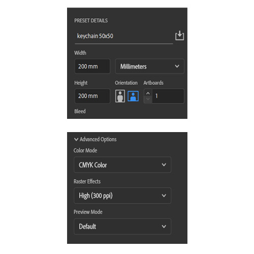
Create your file with any canvas size you want.
In advance option, select color mode to CMYK and raster effects to High (300ppi)
*300ppi = 300dpi
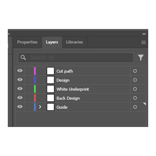
Create these layers:
1) Cut path
2) Design
3) White Underprint
4) Back Design*
5) Guide**Back Design layer is unnecessary if you do not want to print the back side.
*Guide layer is for the the area boundary to place all layers' elements inside.
*Please make sure to arrange the layers in the specified order.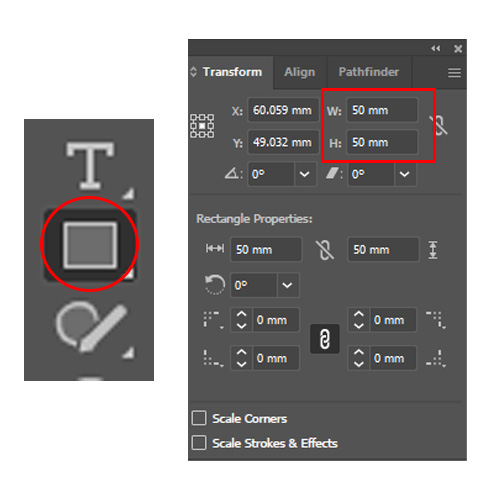
After create the canvas and add layers, use Rectangle tool in the guide layer to create the area on the canvas.
When the shape is created, set the width and height in transform to our compatible size's range.
Check our template for compatible sizes in each products
-
Placing the design
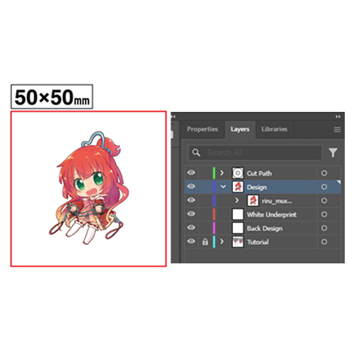
Place your design onto the design layer. (Please merge your design's layers into one element before pasting.)
Make sure your design is properly centered within the area boundaries to ensure accurate printing results.
*The minimum size available inside the boundary area is 12x12mm.
*Do not edit locked layer (If you are using our template.)
*When pasting data, select the target layer before pasting.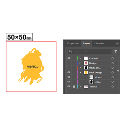
If you want to print on the back side, add your backside design into the Back Design layer and don't forget to align the backside design and the main design in the same position.
All texts and lettering must be created in a mirrored (reversed) orientation. The text will be in the correct orientation when viewed from the back.
Points to note when designing
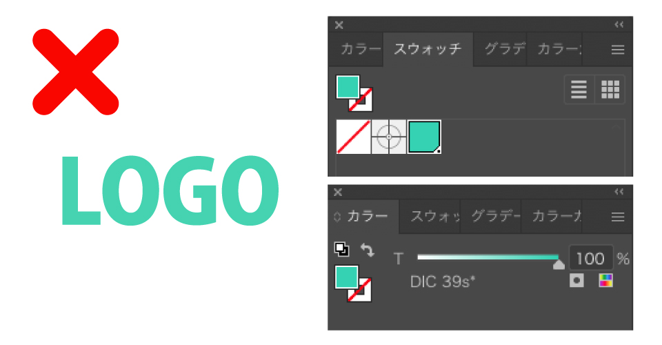
Please make sure to use the CMYK color model when designing
Since using RGB, DIC, or any color models may have a difference in color when printing.
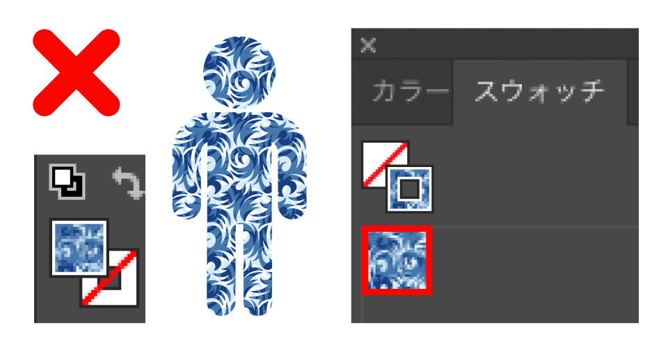
If pattern swatches are used, please be sure to rasterize them. Otherwise, the pattern positioning may shift when we open the file on our end.
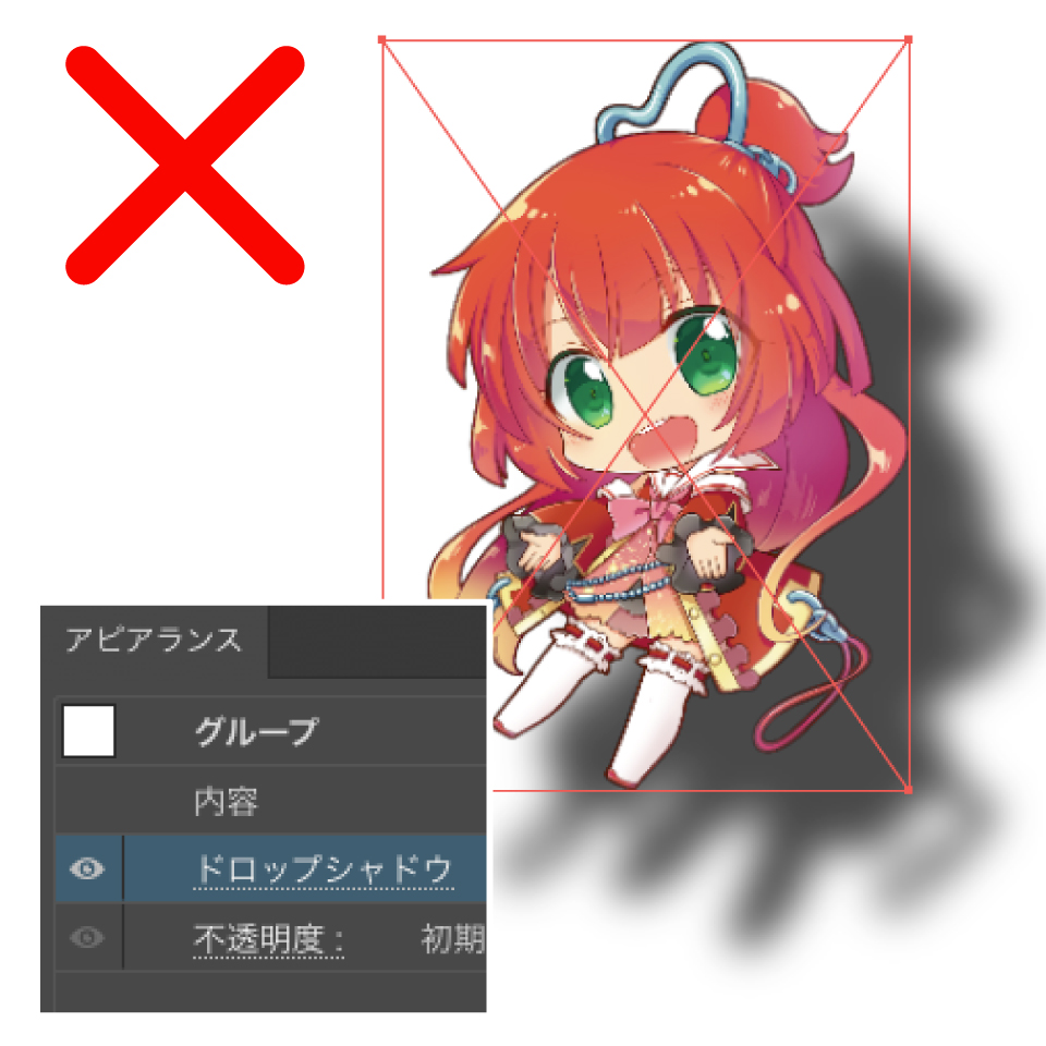
Any applied shadow effects around the must be expanded via Expand Appearance or Rasterize (including Live Paint and similar features).
If there is a defect in the finish because the above is unprocessed, it will not be covered by the initial defect warranty.
*Please note that we may not perform error checks when your data has submitted.
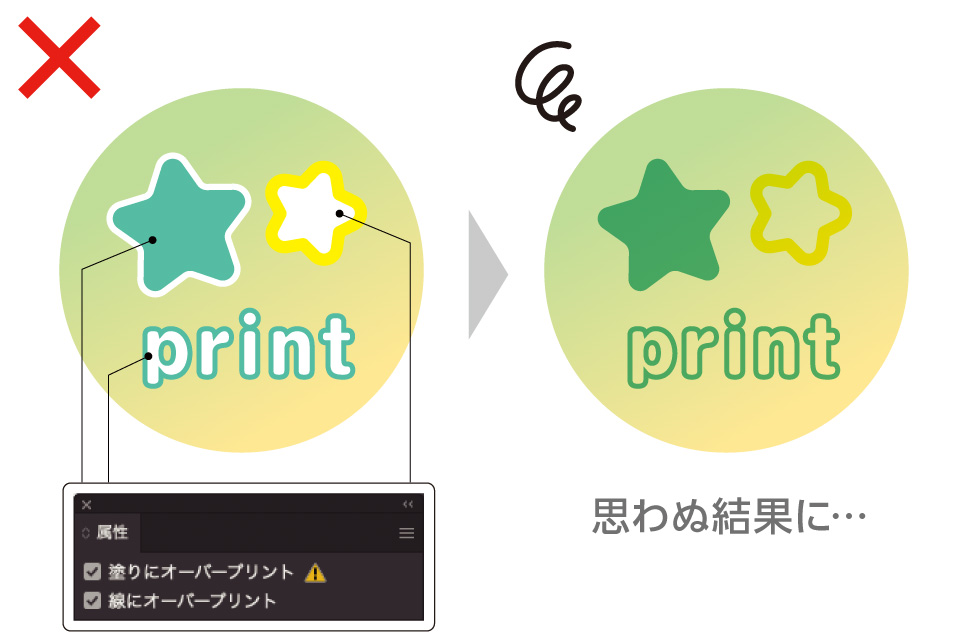
DO NOT use Overprint option settings, as they may result in unexpected printing outcomes.
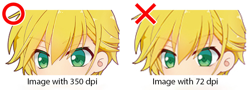
The resolution of the design should be set to 300 dpi or higher before designing or pasting inside the design layer.
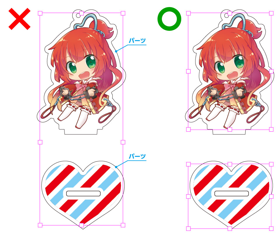
For standees or any products consisting of multiple parts, do not group them into a single object. Ensure that each part of the design is placed separately and remains ungrouped.
-
Making Cut Path
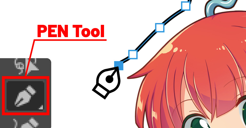
Trace the outer contour of the illustration using the Pen Tool.
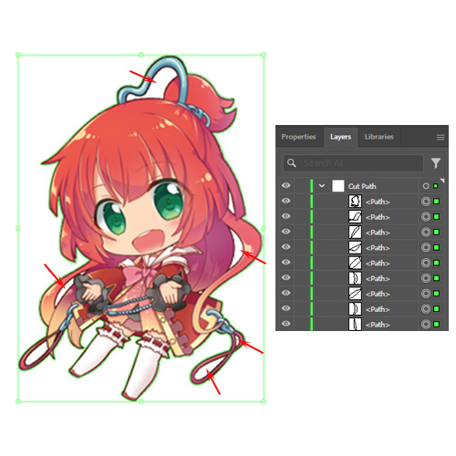
After finished tracing the outer contour of the design, trace the inner part that should be transparent.
*This step is highly recommended for the beautiful printing results especially when creating a human figure design but unnecessary if you want to leave the area fill when making white underprint layer.
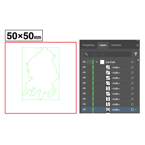
Select and move the outer trace line (from the first step of making cut path) to the lowest layer inside the cut path layer.
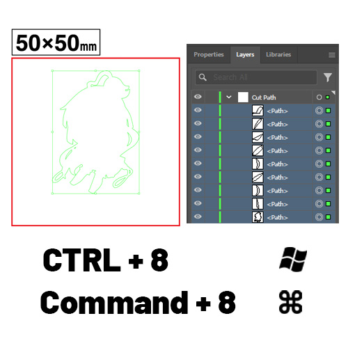
Then select EVERY design's trace lines inside the cut path layer.
After that press CTRL + 8 (for Windows) or Command + 8 (for Macbooks) to compound the trace lines into one element
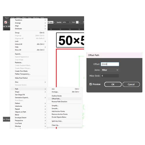
To make the 2mm cut path margin, use offset path option and set the offset value to 2mm
*Offset path setting locate in Object -> Path -> Offset Path
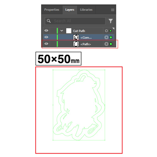
When click OK, the result will be like the example picture.
*The layer needed in this step is the < Path > layer.
*You can use the < Compound > layer for making white underprint.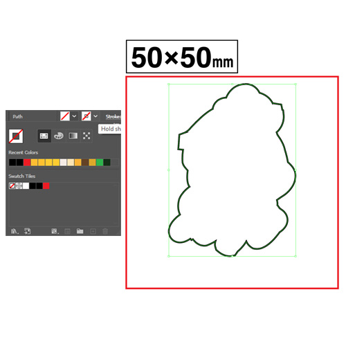
To make the cut path appear, change the stroke color to black with the color menu on the top left.
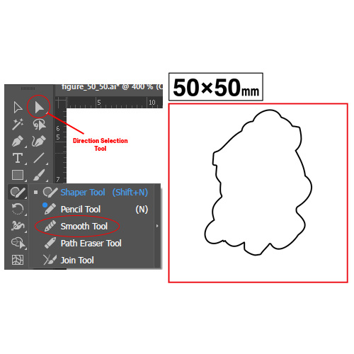
Lastly, smoothen the corner edges by using either Direction Selection Tool or Smooth Tool to prevent unexpected results when cutting acrylic plates.
*Direction Selection Tool is recommended but both tools are useable depends on the your preference.
Attachment hole cut path (for keychains)
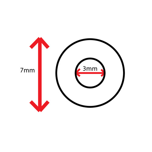
Attachment hole has 3mm diameter for the inner circle, and 7mm diameter for the outer circle.
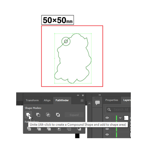
Move the attachement hole's cut path to the desired position on the full body path, then select both cut paths and merge into one object using Pathfinder -> Unite.
(DO NOT select the inner circle when merging)*If you cannot find the Pathfinder box, open Window menu (on the top left) and select Pathfinder or press CTRL + Shift + F9 (for Windows) or Command + Shift + F9 (for Macbooks).
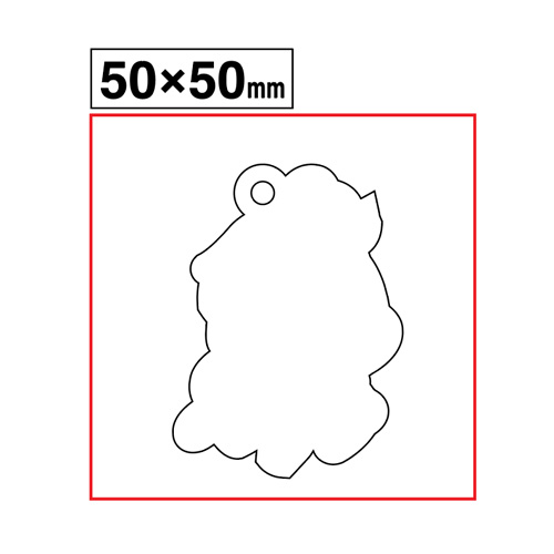
After merging, please make sure that cut path stays inside the red area, it can cause unexpected cutting result if the cut path leave the area.
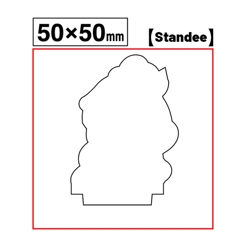
Base plate cut path (for standees)
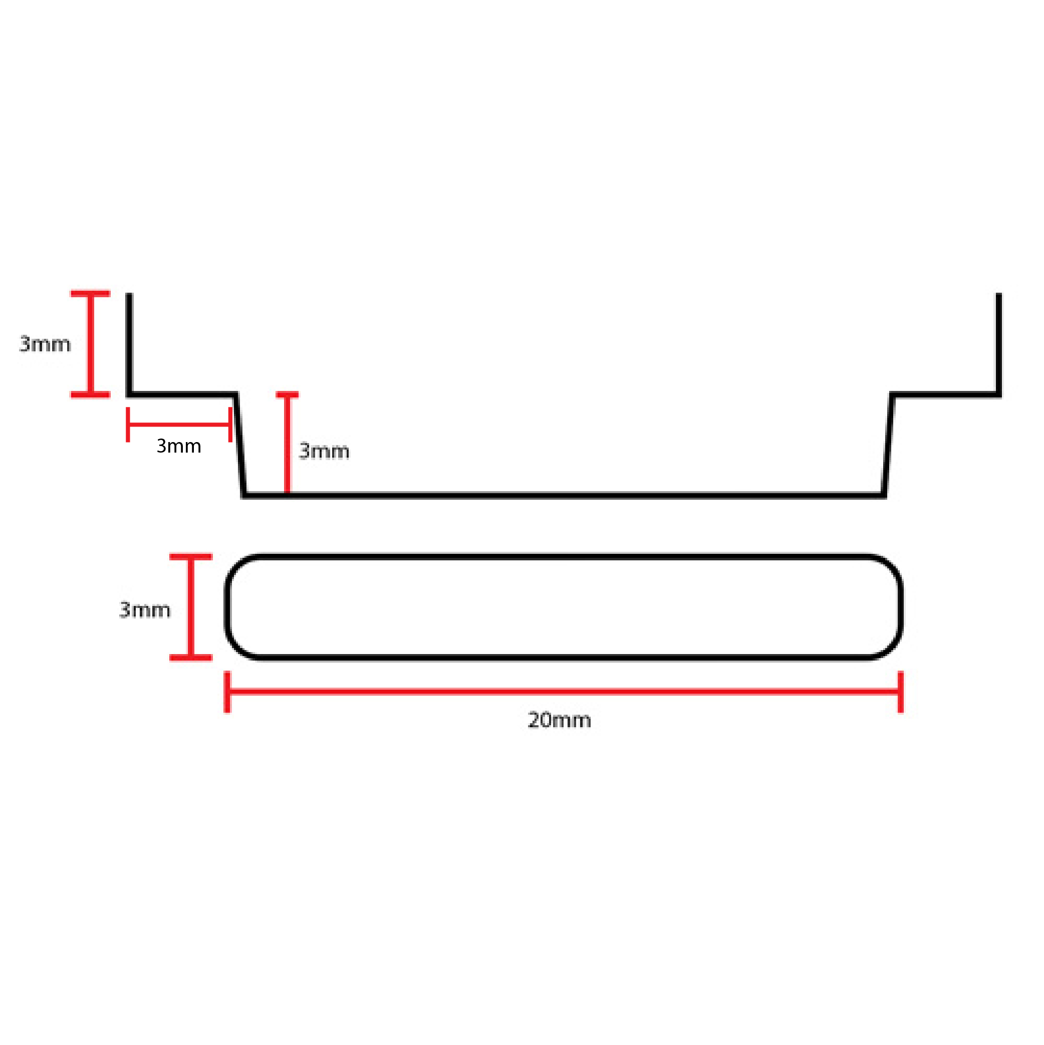
The height of the standee's insertion tab is 6mm total and the insertion hole has 3mm width and 20mm length.
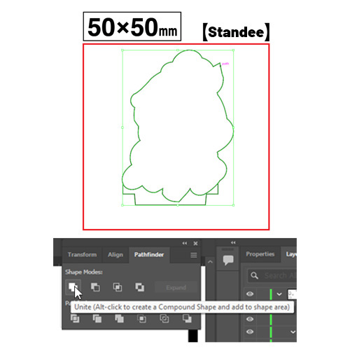
Move the tab cut path to the desired position on the full body path (preferably make the tab cut path connect to the main body cut path completely without leaving any space.)
Then select both cut paths and merge into one object using Pathfinder -> Unite.*If you cannot find the Pathfinder box, open Window menu (on the top left) and select Pathfinder or press CTRL + Shift + F9 (for Windows) or Command + Shift + F9 (for Macbooks).
After merging, please make sure that cut path stays inside the red area, it can cause unexpected cutting result if the cut path leave the area.
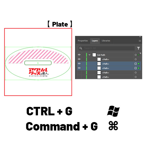
After creating your cut path for standee's plate, move the insertion hole cut path to the design. (Place the hole on the center of the design is highly recommended for overall stability)
Then select both the main plate cut path and the insertion hole cut path and group it using CTRL + G (for Windows) or Command + G (for Macbook)
-
Making White Underprinting
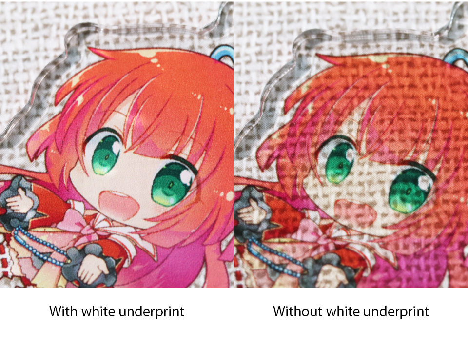
White Underprinting serves as a base layer that enhances the vibrancy of CMYK four-color printing.
Without white underprinting, the final result will have a translucent appearance. (Intentionally omitting white underprinting in certain areas to create a semi-transparent effect is also recommended.)
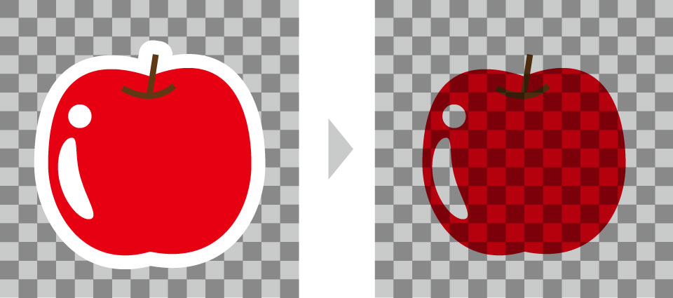
In standard printing, white areas in the design data will not be printed and will appear transparent.
If you wish to show the white areas in your product, please use the White Underprint layer. To express white elements in your design, place your design on both the Design Layer and the White Underprint Layer.
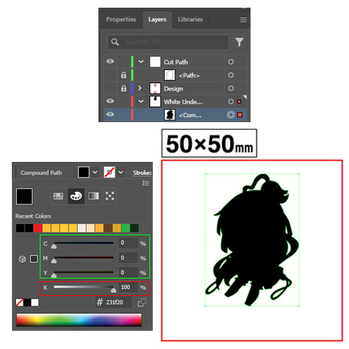
Use the compound layer moved to white underpress layer from the cut path step and fill the black color with the value of K = 100% and C, M and Y value has to be set to 0 for the White Underprint layer.
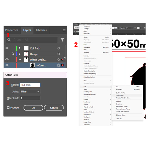
After filling the black color, set offset path to -0.1mm
*Offset path setting locate in Object -> Path -> Offset Path
Important Note when making white underprint layer
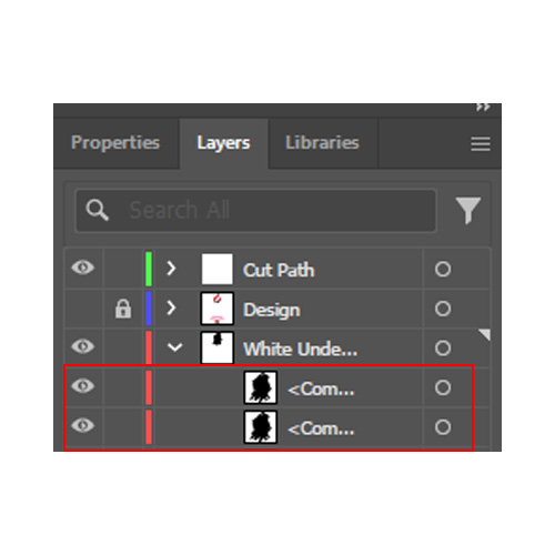
When offset path is set to -0.1mm, it will create another layer inside that may look almost the same.
Turn on/off the eye icon on both layers one at a time to see which one is the one you need for the white underprinting layer. (The smaller one is the one you need for this layer.)
Pre-Submission Checklists
Note: Please read every step carefully to avoid conflicts during the production process.
-
Color Mode
- The color mode of the file must be CMYK only.
- Using RGB or any other color mode may cause the color to change and some features are not available.
*The margin is not needed when you are producing full bleed acrylic products
-
Effects & Patterns
- If you have applied any effects or complicated patterns inside your design, be sure to rasterize the effect and pattern to prevent unintended results
-
Design Resolution
- The appropriate resolution of the design have to be approximately 300 to 350 dpi
- If the resolution is too low, the output will be rough, and blurry and if it is too high, there may be unexpected results during the printing process.
-
Cut Path
- Make sure that the cut path has 2mm or wider margin away from the actual design, the cutting process cannot be proceed if the cut path width is lesser than 2mm.
-
File Names
-
Do not include the following symbols into the file name:
「/」「:」「;」「 *」「?」「"」「 <」「>」「|」「?」
-
Do not include the following symbols into the file name:
-
File Size
- File size with more than 50MB can cause errors in the printing process.
- Please adjust the file size to be lower than 50MB before submitting your data file.
-
Copyright
-
Please make sure you have the right to produce the goods.
Read our Copyright and Violation Expressions
-
Please make sure you have the right to produce the goods.